
AMR conveyor integration guide
AMR Conveyor Interface Design: A 3-Layer Checklist for Transfer, Handshake, and Recovery
Define the physical transfer, control handshake, information handoff, and recovery ownership before design freeze.
An AMR conveyor interface should be defined as three coordinated layers: the physical transfer and docking boundary, the control handshake, and the information handoff across the AMR or fleet manager, conveyor PLC/HMI, and upstream WMS, MES, or WCS. Freezing only the conveyor height or only an I/O list leaves the other two layers open to conflicting assumptions.
Before design freeze, give both the AMR and conveyor suppliers the same version-controlled interface package. It should state what is being transferred, how the equipment aligns, who authorizes movement, what proves completion, which system owns each status, and what happens after a timeout or partial transfer. This article is a supplier-neutral planning method—not a universal protocol, safety design, or statement that a specific HiO configuration is compatible with a particular conveyor.
For the wider site-survey, workflow, system-interface, pilot, and acceptance sequence, use the AMR integration guide. The checklist below concentrates on one boundary within that larger project: the AMR-to-fixed-conveyor handoff.
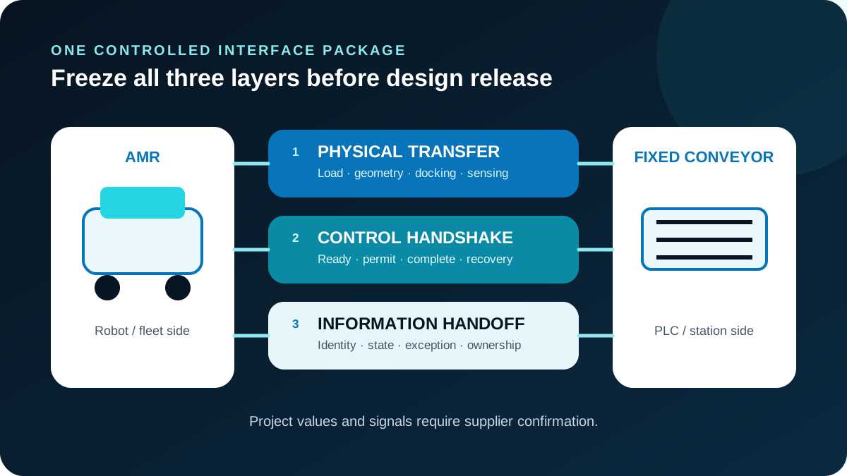
Layer 1 · equipment boundary
Layer 1: Physical transfer and docking
Start with the load, not the robot. Record the load and carrier envelope, mass, center of gravity, underside or support condition, transfer direction, conveyor contact face, and any orientation constraint. Then add the fixed-conveyor height, the allowable project tolerance, the intended docking reference, the load-presence sensing concept, guarding boundaries, maintenance access, and the conditions under which a person may enter the transfer area.
Do not insert a generic tolerance copied from a brochure. The selected suppliers should derive and approve the project values in drawings. Treat docking as a station-level tolerance chain: the AMR, its localization or docking reference, the fixed structure, conveyor, carrier, and load can all affect alignment. A repeatability figure for one component cannot, by itself, establish a successful transfer at the assembled station.
If the project has not yet decided whether material should move by AMR, fixed conveyor, or a hybrid arrangement, settle that earlier architecture question through the AMR vs conveyor decision. This checklist assumes the project has already chosen an AMR-to-conveyor transfer point.
Physical interface sheet
| Input to freeze | What both suppliers need | Acceptance evidence to request |
|---|---|---|
| Load and carrier | Dimensions, mass, center of gravity, rigidity, support surfaces, orientation, overhang and variation by SKU or carrier type | Approved load/carrier envelope and representative test articles |
| Transfer geometry | Direction, elevation, interface face, travel path and the condition at the transfer edge | Coordinated station and equipment drawings |
| Docking reference | Reference feature or marker, approach direction, final pose logic and tolerance ownership | Tolerance analysis and project-specific docking test |
| Detection | Presence, position, clear-to-transfer and transfer-complete sensing concepts | Sensor list, observable states and fault tests |
| Access and boundaries | Guarding interfaces, inspection points, jam-clearing access and maintenance clearance | Risk-assessment outputs and approved work procedures |
The interface sheet is not complete when each supplier has a different drawing. Use one controlled revision, list every open value, name the owner of each value, and require both parties to acknowledge the same revision before detailed design proceeds.
Layer 2 · observable states
Layer 2: The control handshake
The handshake should state which system is authoritative for each state and how that state is observed. A useful neutral sequence is ready → permit → transfer in progress → complete, with explicit fault, timeout, safe-response, and recovery branches. Those names are design vocabulary for the project brief; they are not an industry-wide protocol and should not be copied directly into controls code without supplier confirmation.
For every state, write five things: the owner, the observable signal, the entry condition, the maximum wait or timeout decision, and the response when the expected next state does not arrive. This prevents two common ambiguities: both systems waiting for the other to move, or both systems believing the other has confirmed the transfer.
| State | Question the interface control document must answer | Evidence for acceptance |
|---|---|---|
| Ready | Which equipment is ready, and what physical conditions make that statement true? | Observable input/state with deliberately failed prerequisites |
| Permit | Which side authorizes motion, and can the permit be withdrawn safely? | Permit-source test plus loss-of-permit response |
| Transfer in progress | Who initiates movement, and which system owns the load during the transition? | State-transition log and operator-visible status |
| Complete | What proves the load has fully left one side and arrived on the other? | Sensor sequence and incomplete-transfer test |
| Fault or timeout | Which timer expired or condition failed, and what stops or remains inhibited? | Forced fault/timeout test with the agreed safe response |
| Recovery | Who may isolate, retry, reset, reconcile, or return the equipment to automatic operation? | Role-based recovery procedure and resume test |
Manufacturer documentation can show how one implementation exchanges signals or monitors a transfer, but it cannot establish a universal handshake. The selected equipment suppliers and a competent project risk assessment must confirm the real signal definitions, interlocks, safe responses, and acceptance tests.
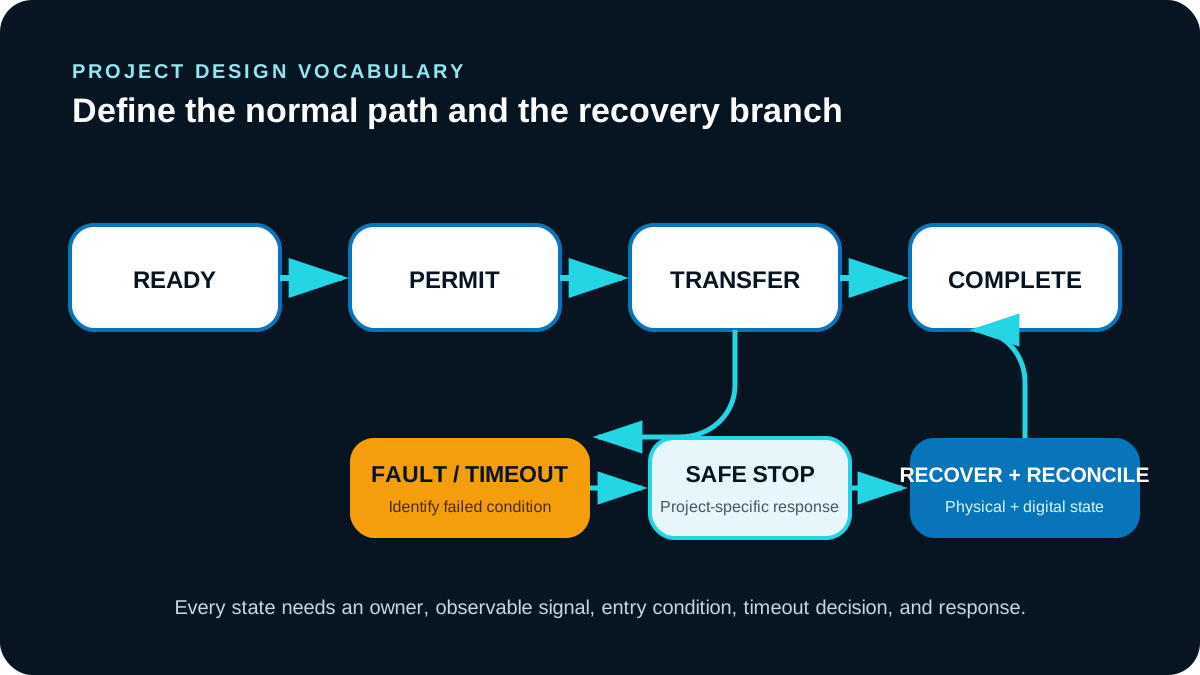
Degraded states · acceptance evidence
Design timeout and recovery before the happy path
A successful transfer is the easy case. The interface becomes testable when it also defines partial transfer, sensor disagreement, communication loss, rejected commands, duplicate messages, timeouts, manual intervention, and power or network restoration.
For each degraded state, separate the physical condition from the digital condition. A load may be physically on the fixed conveyor while the PLC still reports “in progress.” A technician may clear a jam while the fleet manager still assigns the load to the AMR. Resetting hardware without reconciling those records can restart the process with two different system truths.
Use a recovery matrix before controls are finalized:
| Failure condition | Immediate project decision | Recovery ownership to assign | Resume evidence |
|---|---|---|---|
| Load stops between interfaces | Define the project-specific safe response and inhibit further movement | Equipment isolation owner and physical recovery owner | Confirmed load position and clear transfer path |
| Sensors disagree | Hold completion until the disagreement is resolved | Sensor diagnosis owner and state-decision owner | Agreed sensor state or approved manual disposition |
| Permit or completion message is lost | Prevent an uncontrolled repeat command | Controls owner for retry, acknowledgement, and duplicate handling | Reconciled message and equipment states |
| Timeout expires | Identify which motion remains stopped or inhibited | Timer owner, escalation owner, and operator action | Cause cleared and restart criteria satisfied |
| Manual recovery changes load position | Reconcile the equipment and business-system records | Named owner across PLC, fleet, and WMS/MES/WCS | Matching physical, controller, and task state |
The safe response, isolation method, and restart procedure must come from the selected equipment, controls design, and risk assessment. This checklist exposes decisions that need owners; it does not prescribe the safety function or claim that one response fits every application.
Layer 3 · system truth
Layer 3: Information handoff and one system truth
The equipment handshake answers whether a transfer may occur. The information contract answers what the transfer means to the wider operation. Define which system owns the load or carrier identity, source, destination, command, acknowledgement, state, timestamp, exception, retry rule, and operator-visible recovery status.
Use one data dictionary across the AMR or fleet manager, conveyor PLC/HMI, and the WMS, MES, or WCS. The exact fields and system boundaries are project-specific, but every field should still have a source of truth, a consumer, an update condition, and a response to missing, duplicate, delayed, or rejected data.
Information contract checklist
- Identity: What identifies the load, carrier, order, task, source, and destination? Which identifier is authoritative?
- Command and acknowledgement: What instruction starts the process, and what acknowledgement means the command was accepted rather than merely received?
- State: Which system publishes queued, dispatched, arrived, permitted, transferring, complete, faulted, or recovered states?
- Time and sequence: Are timestamps, sequence numbers, or another rule needed to distinguish current from delayed messages?
- Retry and duplicate handling: Can the same command be safely processed again, rejected, or matched to an existing transaction?
- Exception: How are physical faults, controls faults, business-rule rejections, and unavailable destinations distinguished?
- Operator visibility: Where can an operator see the physical condition, controller state, task state, and required next action together?
Do not treat a green status in each separate system as proof that the systems agree. Acceptance should include a traceable sequence showing the physical transfer, handshake transitions, business-system updates, and recovery outcome for both normal and degraded scenarios.
Quotation · design freeze
What to send both suppliers before quotation
A buyer should issue one version-controlled package to the robot, conveyor, controls, and upstream-system parties. It gives each supplier the same assumptions and makes exclusions visible before a quote is compared or a design is frozen.
Include these six input groups:
- 01Load and carrier: dimensions, mass, center of gravity, support condition, orientation, variation, identification method, and representative test articles.
- 02Conveyor and flow: interface height, transfer direction, target operating flow, accumulation assumptions, interface face, and current drawing revision.
- 03Docking and top-module concept: AMR-side transfer concept, station reference, approach, combined tolerance ownership, sensing, and maintenance access. Require the selected supplier to confirm availability and suitability; this article makes no HiO module or compatibility claim.
- 04Controls and system states: AMR/fleet, PLC/HMI, and WMS/MES/WCS owners; ready, permit, in-progress, complete, fault, command, acknowledgement, and exception definitions.
- 05Timeout and recovery: timer ownership, project-specific safe response, isolation, retry authority, manual recovery, reconciliation, escalation, and restart criteria.
- 06Safety and acceptance: responsibility boundaries, risk-assessment inputs, normal and degraded test scenarios, required logs, drawings, I/O or state lists, and sign-off owners.
Ask every supplier to label each input confirmed, requires engineering review, by others, or excluded. That makes quotations easier to compare than a collection of assumptions buried in proposal notes.
Use the manufacturing AMR application review when the interface inputs are defined well enough for a scoped project discussion. That page is the commercial next step; it is not proof that a particular top module, protocol, docking accuracy, throughput, safety function, or conveyor compatibility is available.
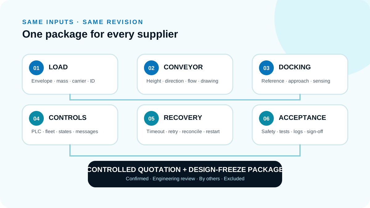
Evidence · boundaries
Sources and limitations
- OMRON LD Platform User Manual — primary manufacturer manual used for transfer monitoring, confirmation, fail-safe interlock, and project risk-assessment boundaries. It describes the LD platform, not a universal conveyor-interface standard.
- Interroll LCP AMR catalog — primary manufacturer catalog used as a supplier-specific example of an AMR-top-to-fixed-conveyor implementation, signal exchange, and docking reference. Its implementation and labels must not be treated as a universal protocol or as evidence of HiO compatibility.
- Industrial Kinetics AMR/AGV pallet interface — supplier solution page used to identify physical, sensing, PLC/HMI, and communications input categories. It is commercially biased, uses AMR/AGV terminology, and does not establish a universal solution.
The source documents available to this draft did not provide a verified visible update date. The article therefore avoids current-model availability, numeric tolerance, docking accuracy, speed, throughput, safety-performance, and compatibility claims. Project values and responsibilities must be confirmed by the selected suppliers and the project's competent controls and risk-assessment team.
Next step · scoped input review
Request an AMR conveyor interface review
Prepare the six inputs above, then request a scoped AMR conveyor interface review. At minimum, bring:
- load and carrier dimensions, mass, and center of gravity;
- conveyor height, direction, and target operating flow;
- the docking and top-module concept under consideration;
- proposed PLC, fleet, and WMS/MES/WCS state owners;
- timeout, retry, and recovery ownership; and
- safety responsibilities and normal/degraded acceptance scenarios.
The discussion can use those inputs to define the project boundary. Final design still depends on supplier drawings, controls engineering, risk assessment, and acceptance testing. No compatibility or performance result is promised by this checklist.